Point‑Supported Glass Canopy
Spider‑Fitting Glass for Frameless Entrance Canopies – Maximum Transparency, Minimal Structure
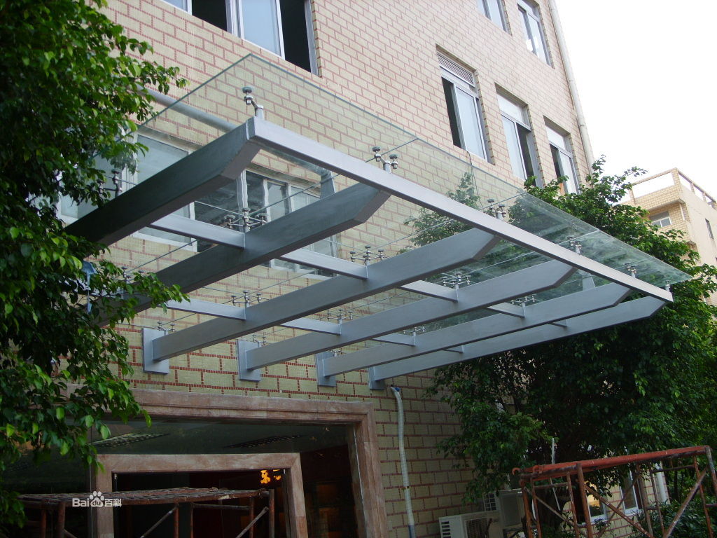
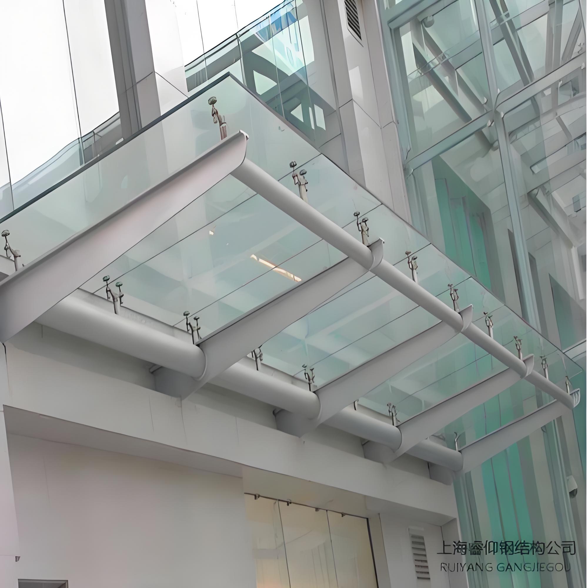
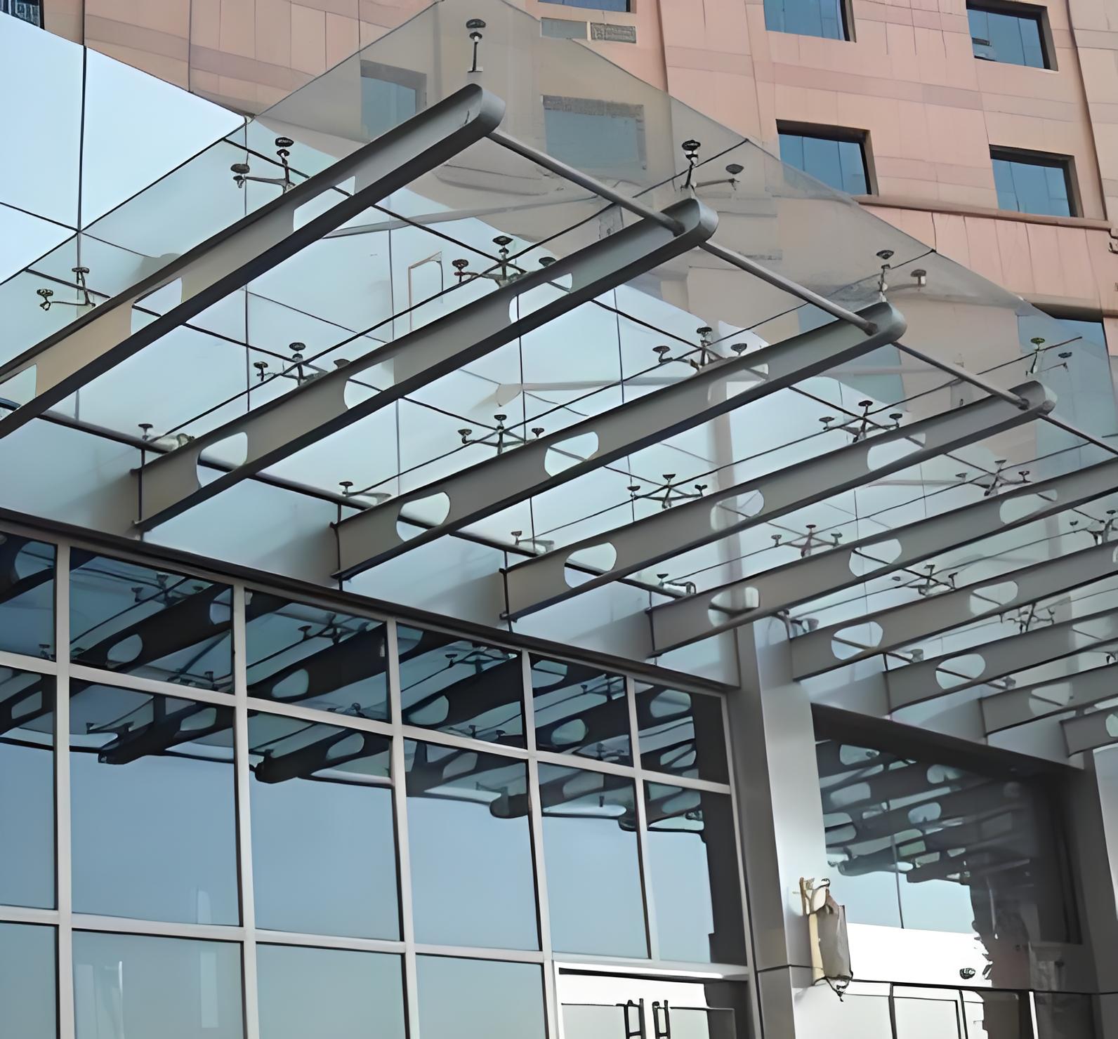
Point‑supported glass canopy refers to glass panels held in place by discrete stainless steel spider fittings at specific points, rather than by continuous perimeter framing. This support method creates a virtually frameless appearance – the glass appears to float, supported only by small, elegant fixing points that become part of the architectural expression.
For procurement managers and glazing contractors supplying hotel entrances, shopping mall atriums, airport drop‑offs, corporate headquarters, and high‑end retail storefronts, point‑supported glass canopies represent the pinnacle of frameless glazing – combining the safety of laminated glass with the visual purity of minimal structural intervention.
💡 Why point‑supported glass for entrance canopies? Point‑supported systems eliminate the visual weight of perimeter framing, allowing the glass itself to become the primary architectural element. The spider fittings – typically machined from 316 stainless steel – become deliberate design features rather than necessary evils. For glass exporters, point‑supported canopy glass commands a 40–80% premium over framed systems due to the precision drilling requirements and tighter tolerances.
1. Quick Specification
| Parameter | Framed Canopy Glass | Point‑Supported Canopy Glass |
|---|
| Support Method | Continuous perimeter frame | Discrete spider fittings (4–8 per panel) |
| Glass Appearance | Frame visible on all edges | Frameless – glass appears to float |
| Hole Drilling | Not required | Essential – CNC‑drilled, ±0.5mm tolerance |
| Glass Build‑Up | Tempered or laminated | Laminated (SGP recommended) |
| Thickness Range | 10–21.52 mm | 17.52–25.52 mm (laminated) |
| Max Size | 3300×18000 mm | 3300×12000 mm (limited by hole pattern) |
| Edge Finish | Flat ground (concealed) | Polished (visible from below) |
| Hardware Integration | Minimal | Integral – holes receive spider fittings |
2. Point‑Supported Glass Canopy Solutions
2.1 Standard Point‑Supported Canopy
- Description: Two tempered plies laminated with PVB or SGP, with CNC‑drilled holes for spider fittings
- Build‑up: 10T + 1.52SGP + 10T (21.52mm) – SGP recommended for point‑supported
- Hole pattern: 4 holes (corners) or 6 holes (corners + mid‑span for larger panels)
- Best for: Standard commercial entrances, retail storefronts
- Key benefit: Frameless appearance at competitive cost
2.2 Heavy‑Duty Point‑Supported Canopy
- Description: Thicker laminated build‑up for larger spans and higher wind loads
- Build‑up: 12T + 1.52SGP + 12T (25.52mm)
- Hole pattern: 6–8 holes (distributed pattern)
- Best for: Large‑span entrances, porte‑cocheres, high wind zones
- Key benefit: Greater span capability without sacrificing frameless appearance
2.3 Low‑Iron Point‑Supported Canopy
- Description: Low‑iron glass with SGP interlayer for maximum clarity
- Build‑up: 10T Low‑Iron + 1.52SGP + 10T Low‑Iron (21.52mm)
- Best for: Luxury hotels, flagship retail, museum entrances
- Key benefit: Water‑white clarity – no green tint at holes or edges
2.4 Jumbo Point‑Supported Canopy
- Description: Extra‑large panels for monumental entrance canopies
- Max size: 3300×12000 mm (limited by hole pattern distribution)
- Build‑up: 12T + 1.52SGP + 12T (25.52mm)
- Hole pattern: 8 holes (distributed across panel)
- Best for: Flagship projects, airport terminals, large‑scale commercial entrances
- Key benefit: Fewer panels, fewer fittings, cleaner appearance
2.5 Point‑Supported IGU Canopy
- Description: Laminated inner pane + argon cavity + tempered outer pane, all point‑supported
- Build‑up: 8T + 1.52SGP + 8T + 16Ar + 8T Low‑E (33.5mm IGU)
- Hole pattern: Through outer pane only (inner pane supported by structural silicone)
- Best for: Heated/cooled entrance canopies with frameless appearance
- Key benefit: Thermal performance + frameless aesthetic
3. Canopy Support Systems – Point‑Supported Details
3.1 Spider Fitting Types
| Fitting Type | Description | Typical Material | Best For |
|---|
| Standard Spider (4‑arm) | Four arms, each with rotule for glass hole | 316 Stainless Steel | Rectangular panels up to 3m × 2m |
| Extended Spider (6‑arm) | Six arms for larger panels or higher loads | 316 Stainless Steel | Large panels, high wind zones |
| Linear Spider | Two arms in line – used at panel edges | 316 Stainless Steel | Continuous runs of point‑supported glass |
| Corner Spider | L‑shaped, fits at panel corner | 316 Stainless Steel | Corner conditions, irregular layouts |
| Adjustable Spider | Articulated arms for sloped or curved canopies | 316 Stainless Steel | Complex geometries |
3.2 Glass Hole Configurations
| Panel Size | Recommended Hole Pattern | Hole Diameter | Counterbore Depth |
|---|
| Up to 3m × 2m | 4 holes (one per corner) | 30–42 mm | 50–75% of glass thickness |
| 3–5m × 2–3m | 6 holes (corners + mid‑span long edges) | 35–50 mm | 50–75% of glass thickness |
| Over 5m × 3m | 8 holes (distributed pattern) | 42–60 mm | 50–75% of glass thickness |
3.3 Rotule (Articulated Connector) Details
| Component | Function | Material |
|---|
| Rotule housing | Receives glass hole, allows rotation | 316 Stainless Steel |
| Spherical washer | Accommodates angular misalignment (±3°) | 316 Stainless Steel |
| Set screw | Secures glass in position | 316 Stainless Steel |
| Neoprene sleeve | Protects glass edge inside hole | EPDM / Neoprene |
⚠️ Critical: The hole diameter must be 2–4 mm larger than the rotule outer diameter to allow for thermal expansion and minor alignment adjustments. This gap is filled with a neoprene sleeve or structural silicone.
3.4 Point‑Supported vs. Other Support Systems
| Factor | Point‑Supported | Cantilever | Framed |
|---|
| Visual appearance | Frameless – fittings visible | Completely frameless | Frame visible on all edges |
| Glass thickness required | 21.52mm (standard) | 25.52mm (minimum) | 10–21.52mm |
| Max span | Up to 4.2m (SGP) | Up to 4.5m | Up to 3m |
| Hole drilling required | ✅ Yes | ❌ No | ❌ No |
| Installation complexity | High (precision alignment) | Very high (structural embedment) | Low (frame‑mounted) |
| Cost premium vs. framed | +40–80% | +60–150% | Baseline |
| Best for | Maximum transparency | Pure minimalist look | Cost‑effective solutions |
4. Glass Configurations – Point‑Supported Canopy Build‑Ups
4.1 Standard Point‑Supported Configurations
| Build‑Up | Total Thickness | Hole Diameter | Max Panel Size | Application |
|---|
| 10T + 1.52PVB + 10T | 21.52 mm | 30–42 mm | 3300×6000 mm | Standard commercial, low wind |
| 10T + 1.52SGP + 10T | 21.52 mm | 30–42 mm | 3300×9000 mm | Standard point‑supported (recommended) |
| 12T + 1.52SGP + 12T | 25.52 mm | 35–50 mm | 3300×12000 mm | Large span, high wind, porte‑cochère |
| 10T LI + 1.52SGP + 10T LI | 21.52 mm | 30–42 mm | 3300×8000 mm | Luxury / low‑iron point‑supported |
| 8T+1.52SGP+8T+16Ar+8T Low‑E | 33.5 mm IGU | 42–60 mm | 3300×8000 mm | Heated/cooled point‑supported |
4.2 SGP vs. PVB for Point‑Supported Canopies
| Property | PVB | SGP (SentryGlas®) | Why It Matters for Point‑Supported |
|---|
| Tear strength | 1× (baseline) | 5× stronger | Higher stress concentration around holes |
| Post‑breakage retention | ~40% | ≥80% | If one ply breaks, remaining structure must hold |
| Creep resistance | Moderate | Excellent | Point‑supported panels experience constant stress at holes |
| Edge stability at holes | May deform over time | Stable | Hole edges must maintain dimensional accuracy |
| Recommended for point‑supported? | ⚠️ Acceptable (low load) | ✅ Mandatory (high load / large span) | — |
⚠️ Recommendation: For all point‑supported canopies with panels larger than 3m × 2m or wind loads above 1.5 kN/m², SGP interlayer is strongly recommended. PVB may be acceptable for small, sheltered point‑supported canopies only.
4.3 Point‑Supported vs. Framed – Structural Comparison
| Factor | Point‑Supported | Framed |
|---|
| Stress concentration | High (at holes) | Low (continuous edge support) |
| Glass thickness required | Thicker (21.52mm minimum) | Thinner (10–12mm possible) |
| Deflection behaviour | Localised around fittings | Uniform across panel |
| Failure mode | Hole‑edge cracking | Edge chipping |
| Redundancy | Depends on hole count | Higher (continuous support) |
5. Safety & Structural Performance – Point‑Supported Canopy Engineering
5.1 Stress Concentration Around Holes
The most critical engineering consideration for point‑supported glass is the stress concentration at the drilled holes. Unlike framed glass (where load is distributed along the entire edge), point‑supported glass transfers all load through discrete points.
| Hole Position | Stress Concentration Factor | Mitigation |
|---|
| Corner holes | 3.0–4.0× nominal stress | Increase edge distance; use larger hole diameter |
| Edge holes (mid‑span) | 2.5–3.5× nominal stress | Reinforce with thicker plies; SGP interlayer |
| Centre holes | 2.0–2.5× nominal stress | Less critical; standard design acceptable |
5.2 Minimum Edge Distances
| Glass Thickness | Min. Distance from Hole Centre to Glass Edge | Min. Distance Between Adjacent Holes |
|---|
| 17.52 mm (8+1.52+8) | ≥35 mm | ≥50 mm |
| 21.52 mm (10+1.52+10) | ≥40 mm | ≥60 mm |
| 25.52 mm (12+1.52+12) | ≥50 mm | ≥70 mm |
5.3 Load Requirements
| Load Type | Typical Value | Point‑Supported Consideration |
|---|
| Dead load (self‑weight) | 54–64 kg/m² (laminated) | Transferred through 4–8 holes – each hole carries significant load |
| Wind load (uplift) | 1.5–4.0 kN/m² | Negative pressure pulls glass away from fittings – critical for point‑supported |
| Wind load (positive) | 1.0–3.0 kN/m² | Positive pressure pushes glass onto fittings |
| Live load (maintenance) | 0.5–1.5 kN/m² | Concentrated load near holes is more critical than for framed glass |
5.4 Deflection Limits
| Standard | Deflection Limit | Point‑Supported Note |
|---|
| EN 16612 | L/200 | Measured at panel centre – local deflection near holes may differ |
| ASTM E1300 | L/175 (recommended) | Conservative for point‑supported |
| IBC §2403 | L/200 (recommended) | Industry standard |
5.5 Impact Performance
| Standard | Test Method | Requirement for Point‑Supported Canopy |
|---|
| EN 12600 | 40 kg pendulum impact | Class 1B1 (no penetration) |
| ANSI Z97.1 | Drop ball impact | Category II (safety glazing) |
| CPSC 16 CFR 1201 | Impact test | Category I or II |
5.6 Thermal Expansion at Holes
| Panel Length | Thermal Movement (±40°C) | Hole Clearance Required |
|---|
| 3000 mm | ±1.2 mm | 2 mm (rotule sleeve accommodates) |
| 6000 mm | ±2.5 mm | 3 mm |
| 9000 mm | ±3.8 mm | 4 mm |
| 12000 mm | ±5.0 mm | 5 mm |
6. Glass Processing for Point‑Supported Canopies
6.1 CNC Hole Drilling – The Critical Process
| Step | Process | Tolerance |
|---|
| 1. Hole position layout | CAD‑generated drilling pattern | ±0.2 mm (CAD) |
| 2. Drill each ply separately | CNC diamond drill | ±0.3 mm per hole |
| 3. Countersinking (if required) | CNC countersink bit | ±0.1 mm depth |
| 4. Edge polishing of hole | Diamond polishing tool | Smooth, chip‑free |
| 5. Alignment check | Laser measurement | ±0.5 mm between plies |
| 6. Lamination | PVB or SGP placed, autoclaved | Holes align within ±0.5 mm |
6.2 Hole Quality Standards
| Parameter | Acceptance Criteria | Why It Matters |
|---|
| Hole diameter | ±0.3 mm | Rotule fit must be precise |
| Hole position | ±0.5 mm from CAD | On‑site alignment of spider fittings |
| Edge quality | No chips >1 mm | Stress concentration at chips can cause failure |
| Countersink depth | ±0.1 mm | Flush fit of rotule head |
| Interlayer alignment | ±0.5 mm between plies | Visual consistency |
6.3 Edge Finishing
| Edge Type | Appearance | Best For | Point‑Supported Note |
|---|
| Polished | Glossy, transparent | All point‑supported canopies | Essential – edges are fully visible |
| Flat Ground | Smooth matte | Not recommended | Edges visible in frameless system |
| Beveled | Angled decorative | Premium point‑supported | Available on request |
6.4 Quality Assurance – Every Point‑Supported Canopy Panel
| Test | Standard | Acceptance Criteria |
|---|
| Dimensional inspection | ISO 9001 | ±0.5 mm |
| Hole position accuracy | CNC verified | ±0.5 mm from CAD |
| Hole diameter | Go/no‑go gauge | ±0.3 mm |
| Edge quality (holes) | Visual + 10× magnification | No chips >1 mm |
| Countersink depth | Depth gauge | ±0.1 mm |
| Flatness inspection | EN 16612 | ≤L/200 |
| Bond strength | EN 14449 | ≥5 N/mm (PVB) / ≥20 N/mm (SGP) |
| Impact test | EN 12600 | Class 1B1 (no penetration) |
| Wind load test | ASTM E1300 / EN 16612 | No fracture at design load |
| Heat soak test | EN 14179 | 4 hrs @ 290°C, ≤0.01% breakage |
7. Maximum Glass Size – Point‑Supported Canopy Capability
| Parameter | Standard Supplier | Jumbo Glass Capability |
|---|
| Max Width | ≤2440 mm | ≤3300 mm |
| Max Length | ≤6000 mm | ≤12000 mm (point‑supported limit) |
| Max Area | ~15 m² | ~40 m² |
| Number of Plies | 1–2 | 2–5 plies |
| Max Thickness (laminated) | 21.52 mm | 44.5 mm |
| Interlayer | PVB only | PVB + SGP |
| Hole Drilling | Manual, ±2 mm | CNC, ±0.5 mm |
| Max Holes per Panel | 4 | 8 (distributed pattern) |
| Edge Finish | Flat ground | Polished |
7.1 Size vs. Load Capacity Matrix (Point‑Supported)
| Build‑Up | Thickness | Max Panel Size (at 2.0 kN/m²) | Hole Pattern |
|---|
| 10T + 1.52PVB + 10T | 21.52 mm | 3300×6000 mm | 4 holes (corners) |
| 10T + 1.52SGP + 10T | 21.52 mm | 3300×9000 mm | 6 holes (corners + mid‑span) |
| 12T + 1.52SGP + 12T | 25.52 mm | 3300×12000 mm | 8 holes (distributed) |
7.2 Why Point‑Supported Limits Differ from Framed
| Factor | Framed Max Size | Point‑Supported Max Size | Reason |
|---|
| Length | 18000 mm | 12000 mm | Stress concentration at holes limits span |
| Width | 3300 mm | 3300 mm | Same limitation (tempering furnace) |
| Area | 59 m² | 40 m² | Fewer support points = higher local stress |
8. Appearance Options
8.1 Glass Substrate
| Option | Appearance | VLT | Best For |
|---|
| Clear | Slight green tint at edges and holes | ~88% | Standard commercial point‑supported |
| Low‑Iron (Ultra Clear) | Water‑white, no green tint at holes | ~91% | Luxury point‑supported canopies |
💡 Note on hole appearance: On standard clear glass, the drilled holes reveal a green ring where the edge of the glass is exposed. On low‑iron glass, the holes are colourless – a subtle but noticeable difference in frameless point‑supported installations.
8.2 Coated Glass (Outer Ply)
| Coating | Effect | Best For |
|---|
| Double Silver Low‑E | Neutral appearance, high insulation | Energy‑conscious point‑supported canopies |
| Triple Silver Low‑E | Maximum solar control | Hot climate point‑supported canopies |
| Reflective (Silver/Gold/Bronze) | Mirror‑like exterior | Architectural statement |
8.3 Spider Fitting Finishes
| Finish | Appearance | Best For |
|---|
| Brushed 316 SS | Matte metallic | Standard point‑supported |
| Polished 316 SS | Mirror finish | Premium / visible fittings |
| Powder‑coated (black/white) | Colour‑matched | Architectural integration |
9. Applicable Glass Products
Each point‑supported canopy configuration links directly to our product pages for detailed specifications.
| Canopy Configuration | Recommended Product | Link |
|---|
| Standard point‑supported canopy | Jumbo Laminated Glass (SGP) | View Product → |
| Budget point‑supported canopy | Jumbo Laminated Glass (PVB) | View Product → |
| Luxury point‑supported canopy | Ultra Clear Tempered Glass | View Product → |
| Heated/cooled point‑supported canopy | Jumbo Insulated Glass | View Product → |
| Large‑format point‑supported canopy | Jumbo Glass | View Product → |
| Point‑supported with coating | Jumbo Low‑E Glass | View Product → |
10. Standards & Certifications
| Standard | Scope | Applicable To |
|---|
| EN 16612 | Glass in building – determination of load resistance | Point‑supported glass design |
| EN 12600 | Pendulum impact test – flat glass | Safety glazing requirement |
| EN 14449 | Laminated glass – product standard | All point‑supported laminated panels |
| EN 12150‑1 | Thermally toughened glass | All tempered plies |
| EN 14179 | Heat soak test | HST for all tempered plies |
| ASTM E1300 | Determining load resistance of glass | US market |
| AS/NZS 1288 | Glass in buildings – selection and installation | Australia / New Zealand |
| ANSI Z97.1 | Safety glazing materials | US market |
| IBC §2406 | Safety glazing | US building code |
| CE | European conformity marking | EU market |
| CCC | China compulsory certification | China market |
| ISO 9001 | Quality management system | Manufacturing process |
Project References
| Project | Country | Point‑Supported Solution | Panel Size | Notable Feature |
|---|
| Singapore Orchard Road Flagship Store | Singapore | 10T LI+1.52SGP+10T LI, 6‑spider | 6200×2400 mm | Low‑iron, polished edges, frameless |
| Guangzhou Airport VIP Entrance | China | 12T+1.52SGP+12T, 8‑spider | 8400×2800 mm | Largest point‑supported canopy, SGP |
| Beijing Wangfujing Mall Entrance | China | 10T+1.52PVB+10T, 4‑spider | 4600×2200 mm | Standard point‑supported, bronze tint |
| Dubai Marina Promenade Canopy | UAE | 12T+1.52SGP+12T, 6‑spider | 6400×2400 mm | Cable + point‑supported hybrid |
| Shanghai Bund Retail Entrance | China | 10T LI+1.52SGP+10T LI, 4‑spider | 5100×2100 mm | Low‑iron, brushed SS fittings |
11. Frequently Asked Questions
Q1: What is a point‑supported glass canopy?
A point‑supported glass canopy uses discrete stainless steel spider fittings at specific points (typically 4–8 per panel) to hold the glass in place, rather than a continuous perimeter frame. This creates a frameless, minimalist appearance where the glass appears to float.
Q2: What type of glass is required for point‑supported canopies?
Laminated glass is required – either PVB or SGP. The glass must be drilled with precision holes that receive the spider fitting rotules. Single‑ply tempered glass is not recommended for point‑supported canopies because it provides no post‑breakage retention.
Q3: Is SGP mandatory for point‑supported glass canopies?
For small, sheltered canopies (panels under 3m × 2m, wind load under 1.5 kN/m²), PVB laminated glass is acceptable. For larger panels, higher wind loads, or any cantilever condition, SGP is strongly recommended due to its superior strength at the stress‑concentrated hole areas.
Q4: How are the holes drilled for spider fittings?
Holes are CNC‑drilled in each glass ply before lamination, with a tolerance of ±0.3 mm per hole and ±0.5 mm positional accuracy. After drilling, the plies are laminated together with the interlayer, ensuring perfect alignment.
Q5: What is the maximum panel size for point‑supported glass?
Up to 3300×12000 mm for 12T+1.52SGP+12T laminated glass with 8‑hole distributed pattern. The length is limited by stress concentration at the holes – beyond 12 metres, the local stresses become too high for safe design.
Q6: Can point‑supported glass be used for sloped canopies?
Yes. Point‑supported systems work well for sloped canopies (up to 45°). The spider fittings can be articulated (using rotules) to accommodate the angle. Additional safety factors apply for sloped installations.
Q7: How many spider fittings are needed per panel?
Typically 4 holes for panels up to 3m × 2m, 6 holes for panels up to 5m × 3m, and 8 holes for larger panels. The number depends on panel size, wind load, and glass thickness.
Q8: Can point‑supported glass be combined with Low‑E coating?
Yes. Low‑E coating can be applied to the outer ply surface. The coating does not interfere with the hole drilling process. Combined point‑supported + Low‑E configurations are available for energy‑efficient entrance canopies.
Q9: How do you prevent water leakage at the spider fitting holes?
Each hole is fitted with a neoprene sleeve or EPDM gasket that seals the gap between the glass and the rotule. The spider fitting itself is designed to shed water away from the hole. For additional protection, a bead of structural silicone can be applied around the fitting.
Q10: Do you supply the spider fittings?
No – we supply the drilled glass panels only. Spider fittings are supplied by specialised hardware manufacturers. We provide detailed hole position drawings (DXF files) that can be shared with your hardware supplier to ensure perfect on‑site alignment.
12. Request Point‑Supported Canopy Glass Quote
Submit your project requirements for a competitive FOB quotation and full engineering assessment.
Required Information:
- Project type: Hotel / Shopping mall / Office building / Retail flagship / Airport / Other
- Canopy type: Point‑supported / Point‑supported + cable / Point‑supported sloped
- Panel dimensions: Width × Length
- Number of panels
- Glass build‑up: e.g., 10T + 1.52SGP + 10T
- Interlayer: PVB / SGP / Unsure (let us advise)
- Glass substrate: Clear / Low‑Iron / Tinted (specify colour)
- Glass thickness per ply: 10mm / 12mm / Custom
- Coating: None / Low‑E / Reflective / Solar control
- Edge finish: Polished (recommended) / Flat ground / Beveled
- Number of holes per panel: 4 / 6 / 8
- Hole diameter required (mm)
- Countersinking required? Yes / No
- Hole position drawing: Provide CAD file or sketch
- Wind load requirement (kN/m²)
- Deflection limit: L/200 (standard) / L/250 / Custom
- Project location
- Certifications required
- Target delivery date
- 📧 Email your specification to: tomron1688@gmail.com
- 🌐 Or upload drawings at: www.jumbotemperedglass.com
- Response time: Preliminary feasibility within 24 hours; detailed quotation with hole pattern verification within 48 hours.
13. Related Pages (Internal Link Cluster)
Within Glass Canopies & Entrance Glazing Section
Product Pages (Cross‑Links)
Other Applications