Home / Jumbo Glass / Jumbo Glass Fin
Jumbo Glass Fin Systems
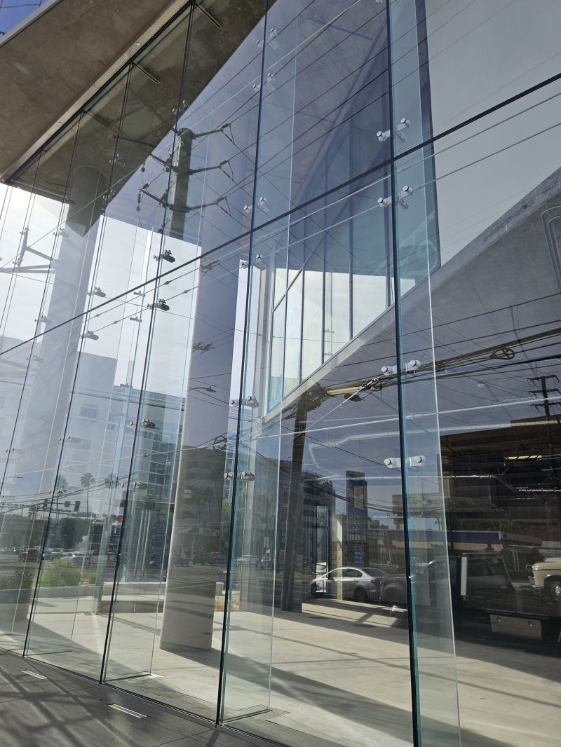
Vertical structural glass fins that replace mullions in all-glass façades and partitions — producing the cleanest, uninterrupted plane of glass. PVB and SGP laminated construction up to 3300×20000mm, engineered as one coordinated fin-and-wall assembly.
Up to 3300×20000mm monolithic laminatedMullion-free façades & partitionsPVB & SGP interlayersHead, base & point connectionHST heat soaking
1. What Is a Glass Fin
A glass fin is a vertical structural glass member that acts as the primary support for a glass wall or façade, replacing the metal mullion that would otherwise divide the opening. The fin carries wind and self-weight loads from the wall panels and transfers them to the building structure at its head and base connections.
Fin, not a mullion
A mullion is a metal (usually aluminium) vertical. A fin is a laminated glass lite doing the same structural job — the reason an all-glass elevation can be truly mullion-free.
Two assembly roles
Façade fin: tall exterior fin supporting an all-glass curtain wall. Partition fin: interior fin creating a frameless office or atrium wall. Both follow the same structural logic.
Rule one — design the fin and wall together. Fin depth, interlayer, connection and wall-panel subdivision are one engineering system. Jumbo Glass supplies the laminated fin and wall build-up; the fixing-system designer and structural engineer define the load path, head/base connection and movement allowance.
2. Why Jumbo Glass Fin
Truly mullion-free
A continuous glass fin removes the vertical metal line, giving the elevation or partition an uninterrupted glass plane from floor to floor.
Fewer joints
Taller fins mean fewer horizontal transoms and connection points across the opening, simplifying the assembly and its weatherline.
One build-up, one record
Fin and wall from one production line, one tolerance set, one quality record — critical when both are oversize laminated glass.
Post-breakage retention
PVB and SGP laminated construction holds the fin after breakage, preserving the structural load path while the failed member is replaced.
Design coherence
Fin, wall, canopy and balustrade can share one laminated glass family and one supply schedule on the same project.
3. Configuration Matrix
Match the project driver to a fin family. The matrix is a decision map, not a product list — exact fin depth and span are confirmed by structural calculation.
| Fin family | Typical build-up | Best for | When to upgrade |
|---|
| Laminated PVB fin | 6+6, 8+8, 10+10 PVB (12.76–25.52mm) | Standard façade and partition fins | Tall fin or high wind → increase ply or SGP |
| Laminated SGP fin | 6+6+6, 8+8+8 SGP (3-ply) | Tall fins, high wind, safety-critical | Concentrated load or生命-safety → 4-ply |
| Single fin | One vertical fin per panel bay | Low- to mid-rise, regular bays | Excessive span → twin fin or deeper build-up |
| Twin / back-to-back fin | Two fins, one each side of wall | High-rise, large panels, high wind | Design load drives spacing and depth |
| Fin + IGU wall | Laminated fin + sealed IGU panels | Conditioned all-glass façade | Sealed IGU panels limited to 3300×12000mm |
| Fin + monolithic wall | Laminated fin + monolithic wall | Atrium, interior, non-conditioned | Overhead or safety role → laminate the wall too |
The fin is detailed alongside the full structural-glass system: see Jumbo Structural Glass for support methods and Jumbo Glass Curtain Wall for the envelope context.
4. Typical Build-ups
PVB fin
12.76mm (6+6 PVB), 17.52mm (8+8) and up. Standard architectural interlayer, suitable for most façade and partition fins.
SGP fin
3-ply and 4-ply SGP constructions where residual strength after breakage and tall-span stiffness are design conditions.
Single fin
One vertical laminated fin per bay; the default for regular, low- to mid-rise assemblies.
Twin / back-to-back
Two fins, one either side of the wall, for high-rise or large-panel designs with high wind loads.
Head & base connection
Shoe or channel capture with gasket and allowance for vertical movement; connection type is part of the RFQ.
Fin + wall assembly
Fin = SGP or PVB; wall = monolithic, laminated or IGU. One project, one coordinated schedule.
Build-up shown here is a specification starting point. Fin depth, interlayer, ply count, connection and total weight must be confirmed by the structural engineer against design wind load, span, wall-panel size, exposure and applicable code. Do not transfer a generic build-up directly to a structural drawing.
5. Jumbo / Oversize Sizing
| Element | Maximum size | Why the limit |
|---|
| Glass fin (monolithic laminated) | 3300×20000mm | Limited only by glass production and handling envelope |
| Wall panel — monolithic / laminated | 3300×20000mm | Limited by production and handling envelope |
| Wall panel — sealed IGU | 3300×12000mm | Handling and long-term edge-seal integrity of the sealed unit
Fin length ≠ wall-panel size. A 3300×20000mm fin is a different engineered object from a 3300×12000mm sealed IGU wall panel. Fin depth and connection are further constrained by headroom, transportation and crane access — all confirmed with the fixing-system designer and structural engineer. State the full fin-and-wall make-up (not just the glass size) when requesting a quotation.
|
6. PVB vs SGP
Both interlayers provide post-breakage retention. The choice is driven by the required residual capacity of the fin after breakage.
| Property | PVB | SGP |
|---|
| Post-breakage stiffness | Standard | Significantly higher |
| Tall fin / high wind | Acceptable within design limits | Preferred for demanding spans and loads |
| Safety-critical fin | Case-dependent | Default specification |
| Typical use | Standard façade & partition fins | Tall fins, high wind,生命-safety zones |
Where the fin must retain load capacity after breakage — tall fins, high wind, walkable adjacency or生命-safety zones — SGP is the engineering choice. The final interlayer is confirmed by the structural engineer.
7. Connection & Assembly
| Connection | Role | Design note |
|---|
| Head capture | Transfers fin load to structure above | Allows vertical movement; defined by fixing designer |
| Base / shoe channel | Anchors fin at floor or sill | Gasket, grout and tolerance part of RFQ |
| Patch / point fixing | Localised connection to wall panels | Hole tolerance and grommet detail required |
| Twin-fin link | Connects back-to-back fins | Spacing and stiffness set by engineer |
Connection type, gasket, movement allowance and finishing are defined before glass manufacture — changes after tempering and lamination are not possible.
8. Structural & Safety
Wind & self-weight
Fin sizing is driven by design wind load, fin depth, span and wall-panel dimensions; calculations follow EN 1991 / ASTM E1300 methodology.
Buckling & deflection
Tall slender fins require buckling and deflection checks; allowable limits are set by the wall system and seal design.
Post-breakage retention
Laminated construction preserves the fin after breakage. SGP provides the higher residual capacity for safety-critical designs.
HST
HST at 554°F (290°C) for 4 hours addresses NiS risk. As a primary structural member, a fin particularly benefits from heat soaking.
9. Processing & Quality
Cutting & edging
Bystronic cutting with ±0.01″ tolerance and controlled edge quality for oversize fins that seat correctly in the shoe and connection.
Tempering
Grenzebach furnace control at ±9℉ for uniform stress and minimal bow across the tallest laminated fins.
Heat soaking
HST at 554°F for 4 hours, with rejection rates below 0.08% on qualified runs.
Traceability & warranty
Production records, SGS-supported processes and a 20-year breakage warranty on qualified products.
Product-level parameters (surface stress, waviness, tolerance) are published on the relevant product pages; this page specifies their application to glass-fin projects.
10. Fin Type vs Assembly
| Fin type | Wall assembly | RFQ must state |
|---|
| Single PVB | Monolithic or laminated wall | Fin depth, span, head/base connection |
| Single SGP | IGU or laminated wall | Wind load, panel size, thermal detailing |
| Twin / back-to-back | IGU wall, large panels | Fin spacing, link detail, high-rise loading |
| Fin + IGU wall | Sealed insulating wall | Wall IGU make-up, fin position (in/out)
Project type→Façade or partition→Wind & loads→Fin depth & span→PVB / SGP→Head/base connection→Wall make-up→RFQ
|
11. Standards Checklist
- EN 1991 — Actions on structures (wind, snow, self-weight, impact).
- EN 13474 / prEN 16612 — Glass in building, design and determination of load resistance.
- ASTM E1300 — Standard practice for determining load resistance of glass.
- ASTM C1405 / C1503 — Structural glass elements and fabricated glass products.
- BS 6262 — Glass in building (general and overhead glazing).
- Fixing / balustrade standards — Confirmed by the responsible design team for the market and application.
This checklist is a specification reminder, not a compliance certificate. The responsible design team confirms the applicable code and approved design regime for each market and project.
12. Decision Flow
① Façade or partition→② Wind & design loads→③ Fin depth & span→④ Single or twin→⑤ PVB or SGP→⑥ Head/base connection→⑦ Wall make-up→⑧ HST & safety→⑨ Engineer review→⑩ RFQ & order
Each step maps to an RFQ field, so the quotation returns with a fin-and-wall build-up that is already engineering-ready rather than a generic price per square metre.
13. Frequently Asked Questions
How big can a jumbo glass fin be?
Jumbo glass fins are supplied as monolithic laminated lites up to 3300×20000mm. The limit is set by glass production and handling, not by a framing catalogue. Actual fin depth and span depend on wall loading, connection at head and base, interlayer (PVB or SGP) and panel subdivision — all confirmed by the project structural engineer.
What does a glass fin actually replace?
A glass fin replaces the vertical mullion of a conventional curtain wall or partition. It acts as the primary vertical structural member supporting the horizontal glass wall, allowing the façade or partition to read as a continuous plane of glass with no metal mullion in the opening.
PVB or SGP for a glass fin?
PVB is the standard interlayer for most architectural fins and provides full post-breakage retention. SGP is specified when the fin must retain significant residual load capacity after breakage — tall fins, high wind loads or safety-critical locations — because its post-breakage stiffness and strength are substantially higher. The choice follows the engineering design, not appearance.
How is a glass fin supported at top and bottom?
Fins are normally captured at head and base in a shoe or channel, or connected through patch fittings or point fixings. The connection must allow for vertical movement and accommodate the load transfer from the wall panels. Connection type, gasket and allowable movement are defined by the fixing-system designer before glass manufacture.
Is heat soaking required for glass fins?
HST at 554°F (290°C) for 4 hours is strongly recommended for tempered glass fins, particularly in overhead, sloped or safety-critical locations. A fin is a primary structural member, so breakage changes the load path of the whole wall and post-breakage retention is a key design condition.
Can glass fins be used with an insulating (IGU) wall?
Yes, but the insulating layer and the structural fin are normally separated to avoid transferring load through a sealed IGU. Common approaches use a monolithic laminated fin on the exterior or interior side, with the IGU wall supported off the fin. Sealed IGU panels within the wall are limited to 3300×12000mm; the fin itself remains up to 3300×20000mm as a monolithic laminated lite.
Specify your glass fin assembly
Send the project type, façade or partition, wind and design loads, fin depth and span, single or twin, PVB/SGP preference, head/base connection, wall make-up and required standards — and receive a coordinated fin-and-wall build-up schedule.
Request specification Explore structural glass Explore curtain wall
Continue reading
System selector for the repeated envelope that often frames the same project as the structural-glass feature.
Walkable and deck glazing — the most demanding SGP and residual-strength application.
Frameless interior walls and balustrades, including point and base support.
Internal Link Cluster
The Jumbo Glass Family (this hub's cluster – do not duplicate content)
Related Product Pages
Applications & Selection Guides
Jumbo Glass Group — Oversized glass fins for commercial and architectural projects. Specifications are starting points and must be verified by a qualified structural engineer against project loads, fin span and depth, connection geometry, exposure and applicable code. Company capability maxima (3300×20000mm monolithic laminated / 3300×12000mm IGU) are not project-specific dimensions.